Tzach's Blog
Ray Casting for Mesh Portion Selection
Ray Casting and Simple Shader Effect
When the team approves a new feature request, you know that something great is about to happen.
The requirement was as simple as selecting a well-defined rectangular portion of the CINE and visualizing its related data.
Let’s break it down.An example for a CINE would look like:

Transform 2D Mouse Coords to 3D World Space
Assume that we are already familiar with how to define a callback to read mouse clicks - then we need to transform these 2D mouse screen coords into the 3D world space.
Ray Casting
We will cast a ray from the mouse point and find any intersection between our ray and the selected mesh in 3D space.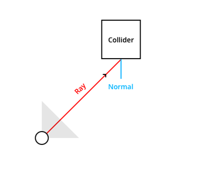

Assume that we have a perspective camera model - then given the camera position, we want to cast a ray in the selected point direction.
So, our ray creation would look like:
std::shared_ptr<Ray> PerspectiveCamera::RayCast(const glm::vec2& point)
{
  const auto& origin{ m_position };
  const auto direction{ Direction(point) };
  return std::make_shared<Ray>(origin, direction);
}
Direction function - projects the 2D coord onto the 3D space as a direction vector:
glm::vec3 PerspectiveCamera::Direction(const glm::vec2& point)
{
  const auto& windowManager{ m_renderManager->Get<core::WindowManager>() };
	const auto& [width, height] { windowManager->GetSize() };
  // Viewport Coords -> NDC.
  glm::vec3 ndc
  {
    (2.0f * point.x) / width - 1.0f,
    1.0f - (2.0f * point.y) / height,
    1.0f
  };
  // NDC -> Clip Space.
  glm::vec4 clip(ndc.x, ndc.y, -1.0f, 1.0f);
  // Clip -> Eye Space.
  glm::vec4 eye { glm::inverse(m_projection) * clip };
  eye = glm::vec4(eye.x, eye.y, -1.0f, 0.0f);
  // Eye -> World Space.
  glm::vec3 world { glm::vec3(glm::inverse(m_view) * eye) };
  return glm::normalize(world);
}
Congratulations! We just created our ray.
Next, we need to find the intersection points between our ray and a mesh collider.
For that we can use an efficient method such as Axis-Aligned Bounding Box.
AABB Collision Detection
For an intuition let’s draw a sketch: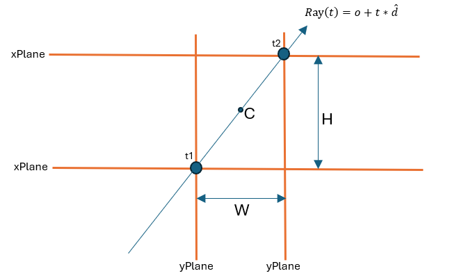
Then, we just want to find the intersection points between the ray and the bounding box defined by the planes, if such exists.
I will demonstrate the calculation for finding t1 within the xy-plane.

To find an intersection point, we just need to find a t1, such that R(t1) intersects with the left border of the bounding box.
Which holds when:

Use the same concept to find t2 as the intersection between the ray and the right border of the bounding box.
Complete implementation:
std::optional<glm::vec3> Ray::Intersects(const std::shared_ptr<Collider>& collider) const
{
		const auto& size{ collider->Size() };
		const auto& position{ collider->Position() };

		const auto min{ position - size / 2.0f };
		const auto max{ position + size / 2.0f };

    const auto inverseDirection{ 1.0f / m_direction };
		const auto t1{ (min - m_origin) * inverseDirection };
		const auto t2{ (max - m_origin) * inverseDirection };

		const auto tMin{ glm::max(glm::max(glm::min(t1.x, t2.x), glm::min(t1.y, t2.y)), glm::min(t1.z, t2.z)) };
		const auto tMax{ glm::min(glm::min(glm::max(t1.x, t2.x), glm::max(t1.y, t2.y)), glm::max(t1.z, t2.z)) };

		// Test for one of the cases:
		// 1. There is no intersection at all.
		// 2. Ray vs AABB intersection is behind of the camera.
		if (tMax < 0.0f || tMin > tMax)
		{
			return std::nullopt;
		}

		return m_origin + tMin * m_direction;
}
That is for the ray vs mesh’s collision detection.
Glowing Effect
Now, we want some effect on the selected portion.
Starting with a vertex shader, where we multiply the mesh’s vertices by the ModelViewProjection transform matrix and preparing the mesh’s vertex position in world space:
#version 410 core
layout (location = 0) in vec3 vertex;
layout (location = 1) in vec2 tex;

out vec2 TexCoord;
out vec4 WorldCoord;

uniform mat4 transform;
uniform mat4 modelTransform;

void main()
{
  gl_Position = transform * vec4(vertex, 1.0f);
	WorldCoord = modelTransform * vec4(vertex, 1.0f);
  TexCoord = tex;
}
Then, for the selected portion we simply mix between the color and its square root during the animation duration:
#version 410 core
in vec2 TexCoord;
in vec4 WorldCoord;

out vec4 FragColor;

uniform sampler2D slice;
uniform sampler1D colorMap;

uniform int numPortions;
uniform float portionSize;
uniform int selectedPortion;

uniform float dt;
uniform float minValue;
uniform float maxValue;

const float epsilon = 1e-5f;

float normalize(float x, float min, float max)
{
    if(abs(max - min) <= epsilon)
    {
        return 0.0f;
    }

    return (x - min) / (max - min);
}

void main()
{
	vec4 index = texture(slice, TexCoord);
	vec4 color = texture(colorMap,
                      normalize(index.r, minValue, maxValue));

	float startPos = -(numPortions / 2) * portionSize;

	float lower = startPos + portionSize * selectedPortion;
	float upper = startPos + portionSize * (selectedPortion + 1);

	bool inRange = WorldCoord.y >= lower && WorldCoord.y <= upper;
	FragColor = inRange ? mix(color, sqrt(color), dt) : color;
}
The Outcome